Treatment
The third page of the UNDO tool is the treatment page, which allows users to input structural treatments, and calculates the amount of nutrient removed by these engineering structures. Users can size the structures, link them to appropriate subregions and create a ‘treatment train’ of structural treatments if desired. The configuration of the export page is shown in Figure 6-1.
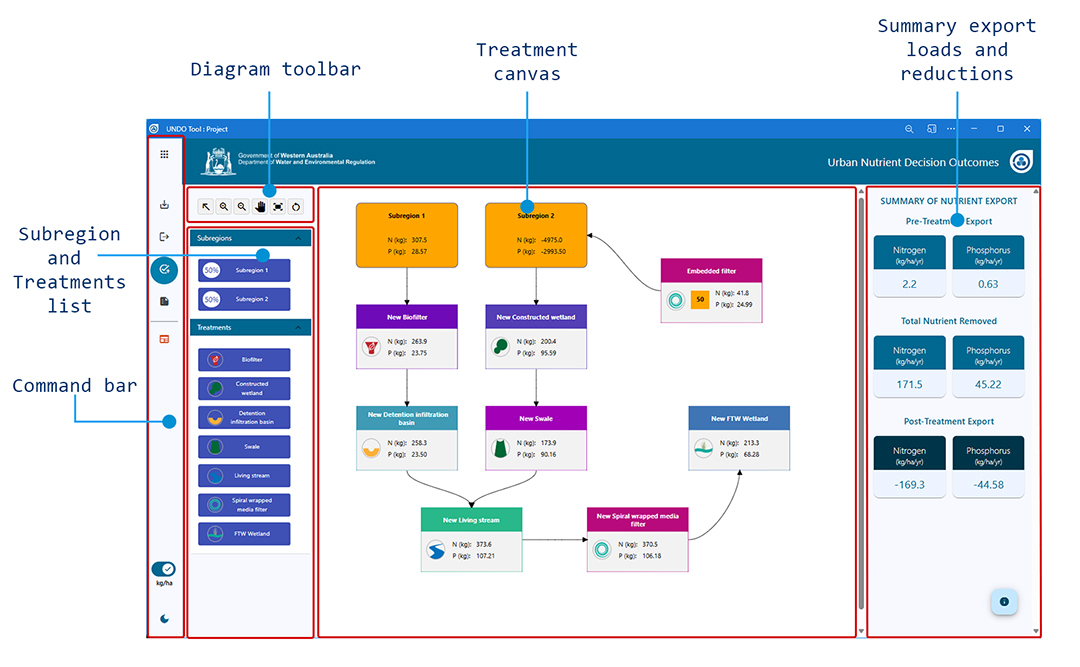
Figure 6-1: Configuration of the UNDO tool treatment page
Structural treatments available in the UNDO tool
The following structural treatments are available in the UNDO tool:
- Biofilters (also referred to as bioretention systems)
- Constructed wetlands
- Swales
- Living streams
- Infiltration/detention basins
- Floating treatment wetlands
- Spiral-wrapped media filters
This section describes the methodology for entering treatments into the UNDO tool and the definition of each treatment (including its best practice design):
Biofilters
Biofilters (also known as biofiltration systems, bioretention systems and rain gardens) are excavated basins or trenches filled with porous filter media and planted with vegetation to remove pollutants from stormwater runoff. They remove nutrients from drainage waters by chemical adsorption, plant uptake and microbial assimilation.
Factors that should be considered in the design of biofilters include:
- their integration into the development’s landscape design
- location as part of planning and design of roads and lots
- vegetation appropriate to the climate and desired pollutant removal
- the impacts of potential acid sulfate soils on filter media and/or structures where relevant.
The Ballee Road biofilter in Busselton is shown in Figure 6-2. For the purposes of UNDO, biofilters must have the following design attributes, with exceptions where noted:
-
Substrate (Payne et al. 2015): Should consist of a stone/mulch layer, a filter layer, and a transition layer. The stone layer should be > 50 mm deep and have no fines. The filter layer should be at least 300 mm deep, and have a hydraulic conductivity in the range of 100–300 mm/hr. This includes clay and silt (< 3%), very fine sand (5–30%), fine sand (10–30%), medium to coarse sand (40–60%), coarse sand (7–10%) and fine gravel (< 3%). The pH should be 5.5–7.5 with at least 3% of low nutrient-content organic matter (< 80 mg/kg orthophosphate, < 1000 mg/kg nitrogen). The soil should be amended with 5% mulch and 5% hardwood chips by volume (optional based on location and depth to groundwater). The transition layer should be at least 100 mm deep, and should be clean, well graded sand with < 2% fines.
-
Plants: At least 50% of the plants should be effective at nutrient removal. The remainder should be local, native, ephemeral plants. There should be 8–12 plants per m2, depending on species. Plants require irrigation in summer months for biofilters to be effective. More information on effective plant species can be found in the Adoption guidelines for stormwater biofilter systems (Payne et al 2015).
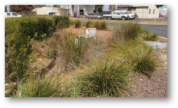
Figure 6-2: Ballee Road biofilter in Busselton
- Biofilters can be unlined or have a lined submerged zone. More information on appropriate biofilter design can be found at:
- Payne, E., Hatt, B., Deletic, A., Dobbie, M., McCarthy, D. and Chandrasena, G. 2015, Adoption guidelines for stormwater biofilter systems, CRC for Water Sensitive Cities, Melbourne, Australia.
- Deletic A, McCarthy D, Chandrasena G, Li Y, Hatt, B, Payne E, Zhang K, Henry R, Kolotelo P, Randjelovic A, Meng Z, Glaister, B, Pham T, Ellerton J. 2014, Biofilters and wetlands for stormwater treatment and harvesting, Cooperative Research Centre for Water Sensitive Cities, Monash University, October 2014.
- FAWB 2009, Adoption guidelines for stormwater biofiltration systems, Facility for Advancing Water Biofiltration, Monash University, June 2009.
Monash University 2014, Vegetation guidelines for stormwater biofilters in the south-west of Western Australia, Monash University, Water for Liveable Cities, Victoria, Australia.
Constructed wetlands
Constructed wetlands are extensively vegetated water bodies that use sedimentation, filtration and biological uptake processes to remove pollutants from stormwater. Significant land areas are usually required to accommodate large detention volumes (generally 1 to 2% of the total catchment area).
Typically, a constructed wetland will include the following design features:
- an inlet gross pollutant trap
- a high flow bypass drain
- inlet zone for energy dissipation and sediment removal
- flow spreaders (porous rock weir) to vegetation bands across shallow wetland to maximise contact of vegetation with flows and promote sedimentation
- a deeper open water body with a submerged vegetation zone, and orifice outlet device to provide controlled release of flow and ensure adequate detention time.
These design features are shown in Figure 6-3 (taken from DoW 2007).
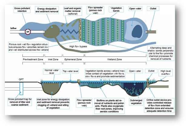
Figure 6-3: Typical schematic plan for a constructed wetland
Constructed wetlands should be separated from groundwater and only constructed in suitable soil conditions. Mosquitoes, midges and acid sulfate soils need to be managed in the design and hydrodynamic conditions should be considered in the design process.
More information on the design and construction of constructed wetlands can be found at:
- Department of Water 2004–07, ‘Section 5.2 of Chapter 9 – Structural controls’, Stormwater management manual for Western Australia, 2004-07, Department of Water, available at http://www.water.wa.gov.au/.
- Engineers Australia 2006, Australian runoff quality: a guide to water sensitive urban design, 2006, Engineers Australia, available at http://www.arq.org.au.
- Melbourne Water 2005, Constructed wetland systems – design guidelines for developers, 3005, Melbourne Water, Victoria.
- Wong, THF, Breen, PF, Somes, NLG & Lloyd, SD 1999, Managing urban water using constructed wetlands, CRC for Catchment Hydrology, Industry report 98/7.
Swales
Swales are grassed or vegetated (typically with Western Australian native plants) broad, shallow channels used to collect and convey stormwater flows, promote infiltration, reduce stormwater peak flow rates and discharge volumes, and remove sediments and nutrients. Swales use a combination of physical and biochemical processes to treat stormwater.
Swales should incorporate the following design factors:
- A longitudinal slope should be selected to avoid scouring, to protect public safety and to prevent excessive periods of stagnant water.
- Vegetation type should be selected considering height and cover, the ability to convey expected flows, aesthetics, pollutant removal and driver visibility (when used in road reserves).
- They should be integrated into landscape design, and their location should be considered with regard to underground services.
An example of a vegetated roadside swale from the City of Subiaco is shown in Figure 6-4.
Swales differ from biofilters in WA in that they do not have strict soil media design constraints or strict plant species constraints. This may make them cheaper than biofilters but they do not treat nutrients (particularly phosphorus) as efficiently as biofilters. More information on the design of swales can be found in the following documents:
- Department of Water 2004–07, ‘Section 4.1 of Chapter 9 – Structural controls’, Stormwater management manual for Western Australia, 2004-07, Department of Water, available at http://www.water.wa.gov.au.
- Engineers Australia 2006, Australian runoff quality: a guide to water sensitive urban design, 2006, Engineers Australia, available at http://www.arq.org.au/.
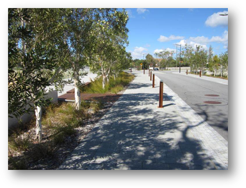
Figure 6-4: Vegetated swale in the City of Subiaco
Living streams
A living stream is a constructed or retrofitted stormwater conveyance channel that mimics the characteristics (morphology and vegetation) of a natural stream. As well as conveying stormwater, they treat it using physical and biological processes and create diverse habitats for wildlife. They can become complex ecosystems that support a wide range of plants and animals.
Some factors to consider in the design of living streams include:
- They should be integrated with the landscape design of the public open space.
- The terrain (particularly the slope) and the geology of the landscape should be considered.
- They should not intersect the dry season watertable.
A typical cross-section of a living stream is shown in Figure 6-5 (note that active public open space such as playgrounds, parks and ovals can be integrated in the 5–100 year bank level in a living stream design; this is not demonstrated in Figure 6-5).
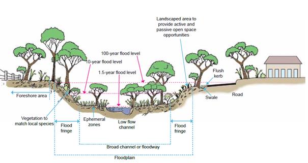
Figure 6-5: Typical cross-section of a living stream
More information on the design of living streams can be found in the following documents:
- Department of Water 2004–07, ‘Section 4.3 of Chapter 9 – Structural controls’, Stormwater management manual for Western Australia, 2004-07, Department of Water, available at http://www.water.wa.gov.au.
- Engineers Australia 2006, Australian runoff quality: a guide to water sensitive urban design, 2006, Engineers Australia, available at http://www.arq.org.au/.
Infiltration/detention basins
Nutrient processing in the UNDO tool is similar for infiltration systems and dry/ephemeral detention areas so they are lumped into a single treatment option.
Dry/ephemeral detention basins are landscaped areas formed by simple dam walls, by excavation below ground level or by using or enhancing natural swales or depressions. These areas primarily serve to capture and store stormwater to prevent excessive runoff and channel erosion in receiving environments, and as areas to remove particulate-based contaminants and sediment. Infiltration basins are depressions designed to capture stormwater before infiltration into the soil profile. They are effective on sandy soils, simple to construct and can be constructed as linear trenches in confined areas.
Both infiltration systems and dry/ephemeral detention areas have a base level at or above the long-term maximum regional groundwater level, with the area inundated as a result of intermittent stormwater inundation rather than as a result of groundwater exposure.
Infiltration systems and dry/ephemeral detention areas are often multiple-use, with these areas used for recreation during dry periods and for stormwater detention or infiltration during periods of rainfall (figure 6-6). They need to be designed for mosquito breeding prevention so that no water will pond after 96 hours.
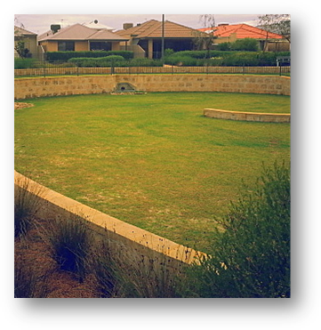
Figure 6-6: A typical infiltration/detention basin on the Swan Coastal Plain
More information on the design of infiltration systems and dry/ephemeral detention basins can be found in the documents:
- Department of Water 2004–07, ‘Sections 3.1 and 5.1 of Chapter 9 – Structural controls’, Stormwater management manual for Western Australia, 2004-07, Department of Water, available at http://www.water.wa.gov.au.
Floating treatment wetlands
Floating treatment wetlands consists of a buoyant media that is planted with vegetation (such as rushes and sedges) and are used to improve the water quality of open water areas, such as lakes, compensation basins and rivers. Plant roots are encouraged to grow within the water column, taking up nutrients within the water, entrain sediments and provide a surface for biofilm growth. Surface vegetation requires periodic harvesting, removing accumulated nutrients in the process.
Floating treatment wetlands are a commercially available product. Manufacturers may provide site specific design and operation recommendations. The following are general recommendations for most floating treatment wetland applications:
- Floating treatment wetlands are recommended to cover 50% of open water areas.
- The placement of floating treatment wetlands should be such to minimise stormwater shortcutting and maximise exposure time.
- Floating treatment wetlands should ideally be placed in permanent water bodies or have a maintenance regime tailored to ephemeral conditions.
- Periodic maintenance is required, which may include vegetation harvesting, replanting and floating wetland placement.
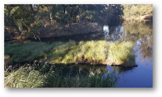
Figure 6-7: Floating treatment wetlands, photo courtesy of SPEL environmental.
Spiral wrapped media filters
Spiral wrapped media filters (SWM filters) are a stormwater treatment that physically and chemically removes nutrients from stormwater. Filters can consist of wrapped, porous geotextile material. Spiral wrapped media filters are used in conjunction with gross pollutant trap pre-treatment and baffled stormwater detention. Filters are considered to be a tertiary level treatment and should be accompanied by pre-treatment to minimise high sediment loads and gross pollutants reaching the filter tanks.
A regular maintenance regime is recommended to maintain optimal performance. This would typically include a 6 month inspection and education of any accumulated sediment on the base of the tank. Replacement of the filters is recommended only when hydraulic conductivity reaches the stage where water can no longer pass through the filters (typically >5 years).

Figure 6-8: Schematic of spiral wrapped media filter installation (Drapper & Hornebuckle 2015).
Using the treatment canvas
The treatment canvas allows for quick and easy assessment of a variety of nutrient treatment configurations. Structural treatments are entered by dragging the relevant subregion and the desired treatment from the ‘subregion and treatment list’, and dropping onto the ‘treatment canvas’ (Figure 6-1). Users can then connect the subregion to the treatment by clicking inside the subregion icon, and dragging the connector to the centre of the treatment icon. The UNDO tool allows a ‘treatment train’ approach to implementing structural treatments. This means that water and nutrients exported from a subregion can flow through a series of treatments, with each treatment removing a proportion of nutrients as the water passes through. Other subregions can connect to either the beginning of the treatment train, or to any point within the train.
Two basic methods are used in the UNDO user interface to represent treatments:
- embedded treatments
- sequential treatments.
Figure 6-9 shows an example of a treatment train that includes two embedded treatment types (a biofilter which receives impervious runoff from 200 lots, and a dry ephemeral detention area that the piped drainage overflows to) and two sequential treatments which form a treatment train (and end-of-pipe biofilter flowing to a living stream).
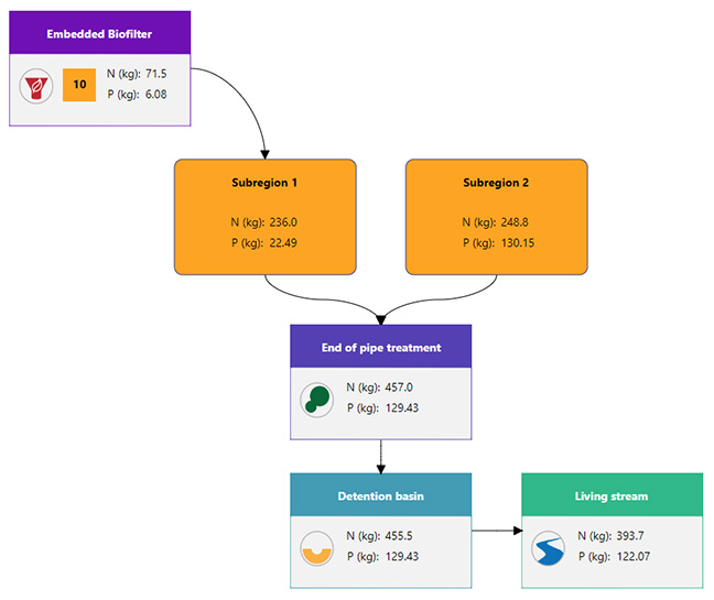
Figure 6-9: Nutrient treatment canvas with a configured treatment train for the UNDO tool
Embedded treatments
Embedded treatments are spread throughout a subregion, and treat a fraction of the subregion. For example, tree-pits can be represented by small bioretention systems (provided they have adequate substrate) that treat impervious runoff from a road or carpark section. In some cases there may be many of these identical treatments in a subregion. Rather than creating a new subregion for each tree-pit, the UNDO tool allows for users to embed these treatments and create many replicas of this treatment within a subregion.
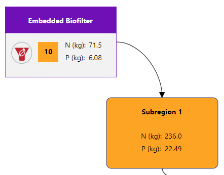
To enter an embedded treatment, from the treatment canvas users simply connect the treatment icon to the subregion icon in that order. Embedded treatments have an orange number box displayed to their right showing the number of replicates of this treatment within the subarea, which differentiates them from sequential treatments. They also are displayed with the name of the treatment on the top of the icon, the mass of nitrogen and phosphorus removed (in kg) and a symbol at the bottom of the icon to represent the type of embedded treatment (Figure 6-10a).
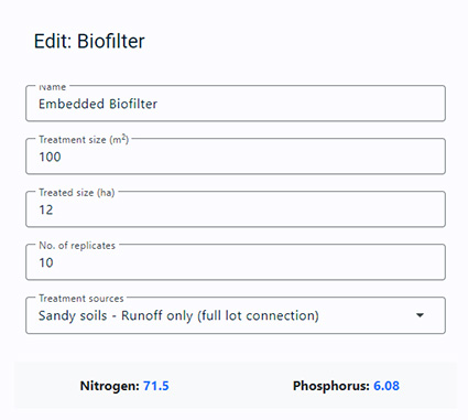
To configure a treatment (embedded or sequential), the user double-clicks the treatment icon. The configuration of an embedded treatment is shown in Figure 6-10b.
(a)
(b)
Figure 6-10: a) Embedded treatment icon, and b) configuration of embedded treatment in UNDO
The user is required edit five text boxes in the treatment configuration:
- Name: This is the name given to a certain type of treatment. They will be defaulted to Biofilter 1, Biofilter 2, etc., though the user may want to be more explicit about naming treatments (e.g. Liege St rain garden) which may be useful when describing the UNDO tool development in the local water management strategy document.
- Treatment size (m2):This refers to the surface area of the treatment. The UNDO tool makes some assumptions about the remaining dimensions of the treatment so the area is the treatment’s only design aspect that the user must enter (for more information see the UNDO tool technical manual).
- Treated size (ha): This is the total area that drains to the nutrient treatment from a particular subregion. This is irrespective of whether it treats only the impervious area or all flow sources. For example, if a residential block discharges to a biofilter but only the impervious area is treated by the biofilter, the entire area of the block needs to be entered into this section. The treatment module of the UNDO tool decides the split between impervious/subsoil and deep groundwater flow.
- No. of replicates: This refers to the number of identical treatments (same treatment size, drainage type and treated area) in the subregion.
- Inflow source(s): This will only appear for in-line treatments (biofilters, spiral-wrapped media filters, swales, and detention/infiltration basins) and refers to the component of the drainage that enters the treatment (runoff only, subsoil drainage, etc.). Four options are available from a drop-down menu. These are described in detail in the following section.
The embedded treatment icon will show the total amount of nitrogen and phosphorus (in kg) removed from the sum of the embedded treatments. The treated size multiplied by the number of replicates must be smaller than or equal to the size of the subregion. There may be more than one type of embedded treatment in a subregion (e.g. a subregion can have embedded swales and embedded biofilters).
Sequential treatments
Sequential treatments differ from embedded treatments in that the entire subregion will discharge to the treatment, and only one sequential treatment will be allowed per subregion. Sequential treatments can be connected to form a ‘treatment-train’ where two or more sequential treatments are joined. An example of a treatment train is shown in Figure 6-1 where the ‘end-of-pipe treatment’ biofilter flows to a living stream. Multiple subregions can discharge to a single sequential treatment, and additional subregions can connect to any treatment on a treatment train (e.g. in Figure 6-1 the public open space discharges to the living stream only).
If sequential treatments are used in UNDO, subregions must be configured so that the entire subregion will flow to the sequential treatment. This is outlined in detail in Appendix A: A guide to configuring subregions in the UNDO tool.
Inflow sources
UNDO treatments are broadly divided into two categories, 1) end-of-pipe treatments and 2) in-line treatments. End of pipe treatments generally treat all of the water that is delivered from a subregion, and includes Constructed Wetlands, Floating Treatment Wetlands and Living Streams. The remaining treatments (biofilters, detention/infiltration basins, swales, and spiral wrapped media filters) are classed as in-line treatments. Inline treatments generally do not treat groundwater, and rely on inflow from pipes (stormwater or subsoil pipes) or from overland runoff.
The source of the flow for in-line treatments will affect how much of the total nutrient from the upstream catchment that it will
Structural treatments can be designed to receive inflows from either impervious runoff or a combination of impervious runoff, subsoil drainage and groundwater drainage. To allow for different inflow treatment configurations in the UNDO tool, structural treatments have the option to treat various components of the flow. These include:
-
Sandy soils – Runoff only (infiltration on lots): This option is selected when the treatment system receives inflows from impervious runoff only, and all house lots that are connected to the treatment infiltrate the first 15mm of rainfall on site. The treatment efficiency is relatively low (see figure 6-1) for these systems, as a large proportion of the total flow is bypassed – it infiltrates to the groundwater and is not treated by the structure (however, treatment can occur via the soils more efficiently in these systems where the soils have a medium to high PRI value). This option is also selected if the BMP treats runoff only in sandy catchment on POS or parkland. When using this treatment type with embedded treatments, it is important that the treated area entered includes the entire catchment of the treatment, as opposed to the impervious area only.
-
Sandy soils – Runoff only (full lot connection): This option is selected when the treatment system receives inflows from impervious runoff only, and all house lots that are connected to the treatment are fully connected to the stormwater system. The treatment efficiency for these systems is medium, as more of the water is routed through the structure (however, there is not the opportunity of this water to be treated by the soils matrix, which occurs in infiltration on lot systems) – however some water is still bypassed – for example the pervious areas of the catchment – as the majority of the rainfall will infiltrate to the groundwater in these areas and will not be treated by the BMP. This option is also selected if the BMP treats road runoff only, and the road reserve has a pit-and-pipe system. When using this treatment type with embedded treatments, it is important that the treated area entered includes the entire catchment of the treatment, not just the impervious area).
-
Sandy soils – runoff and subsoil drainage: This solution is only available for subregions that use subsoil drains. The subsoil drains can be connected directly to the BMP as an inflow, or (more commonly) the subsoil drainage system is connected to a pit-and-pipe stormwater system which will discharge to these BMPs. The treatment efficiency for these systems is medium, as more of the water is routed through the structure – as a large proportion of the water that infiltrated and is picked up by subsoil drains is re-routed to these treatment (in these situations there is the opportunity of this water to be treated by the soil matrix, and again by the structural treatment) – however some water is still bypassed which flows in the regional groundwater system and is not picked up by the subsoil drains. In-line treatment systems are not designed to treat regional groundwater, so this option is not available.
-
Heavy soils – runoff: This option is for heavy (i.e. clays or clayey loam) soils that incorporate a piped or surface water drainage stormwater system. The soils have limited infiltration capacity, and almost all of the runoff is routed to the BMP. Therefore they have a very high treatment efficiency. This is similar to the hydrological conceptualisation used in MUSIC (eWater 2012), and the amount of treatment will be identical to that in a standard MUSIC model (with parameters taken from the UNDO tool technical guide).
A summary of the drainage components available to each of the structural treatments in the UNDO tool is shown in Figure 6-11.
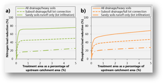
Figure 6-11: Efficiencies of various inflow sources of drainage for inline treatments in the UNDO tool